How to Install Ring Access Controller Pro 2
The following steps outline the install instructions for Ring Access Controller Pro 2. Professional installation is recommended for Ring Access Controller Pro 2 due to the need for electrical wiring.
Installation
Step 1: Confirm Kit Contents
A. 1 x 8 pin, 3.5mm pitch KF2EDGK
B. 1 x USB 5V DC wall supply
C. 1 x 5ft micro USB cable
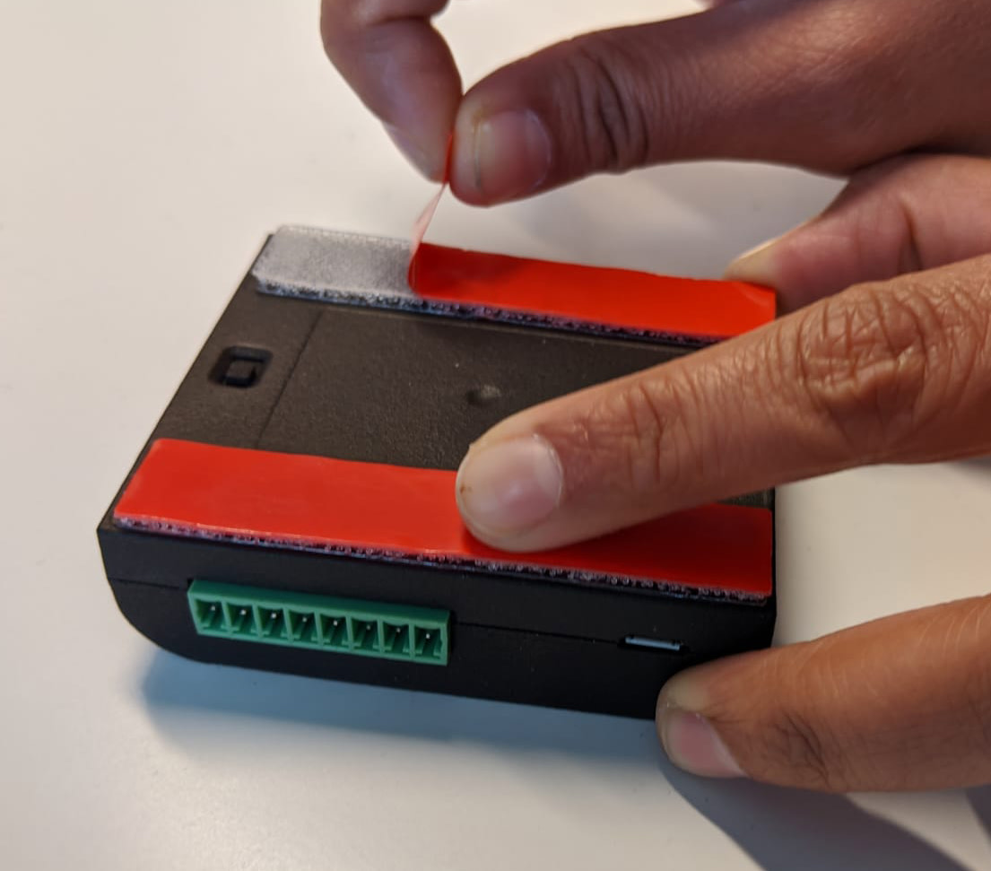
D. 2 x 3M Stretch Release Adhesive
E. 4 x Cable labels
F. 1 x Puck Antenna
G. 1 x Ring Access Controller Pro 2 Device
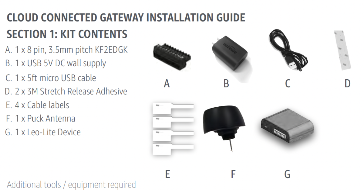
Additional tools / Equipment required
- Wires (18-22 AWG)/ Cables for connector terminals
- Crimp-on terminal connectors
- Optional: RJ45 Ethernet Cable (length less than or equal to 3 meters)
- Optional: PVC Junction Box (if installed outside of the call box or existing junction box)
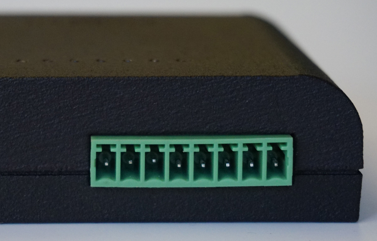
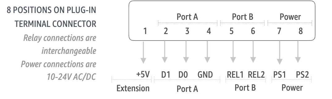
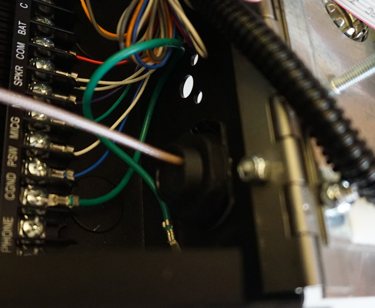
Step 2: Wire installation - Plug-in terminal
- Turn off power at the source.
- Strip insulation to expose about 0.25” of wire (18 - 22 AWG).
- Use flat head screw driver to release screws on 8 pin plug in terminal connector.
- Place each wire in desired opening.
- 7 and 8: positive and negative terminals are interchangeable (polarity agnostic).
- Tighten screw to hold wire in place, tug on wire to ensure it is secure.
- Repeat for all additional wires.
- Connect to desired access control terminals.
- Plug in 8 pin connector to mating connector on the device.
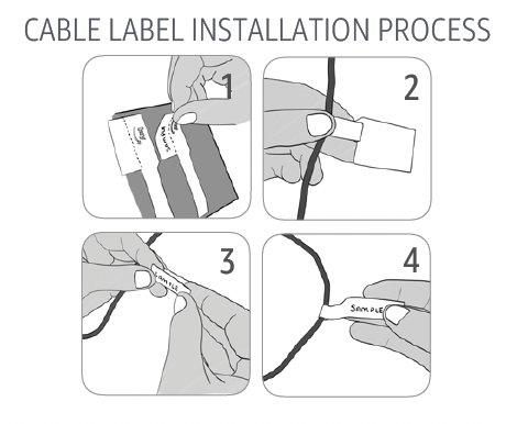
- Use cable labels to identify wires appropriately.
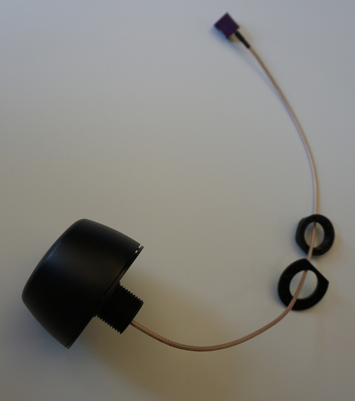
Step 3: Antenna Connection
Puck Antenna
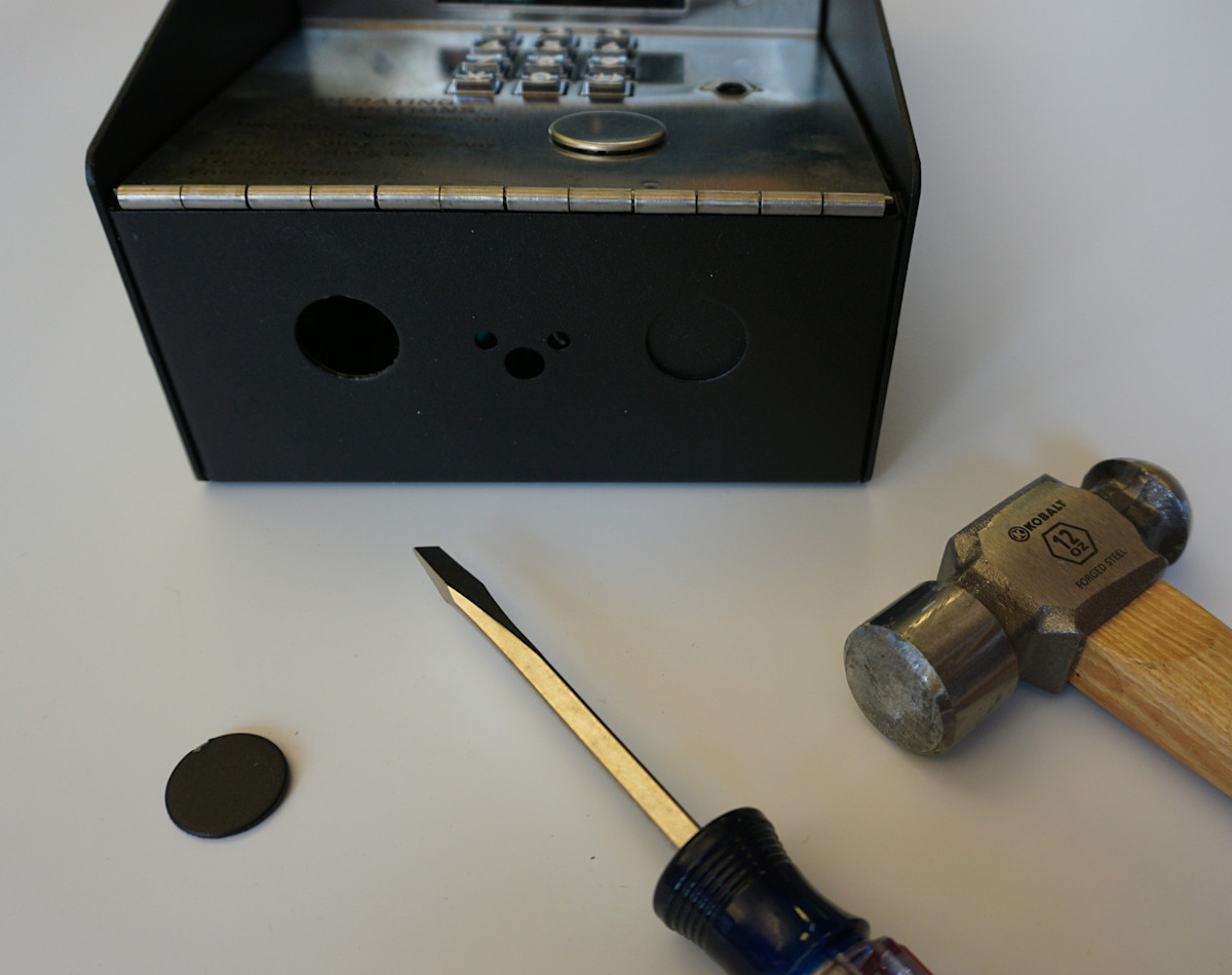
1. Identify a knockout that is at least 1/2" away from the wall and the antenna wire will reach your Ring Access Controller Pro 2 installation location.
2. Unscrew the nut and remove washer from puck antenna.
3. Remove knockout on the call box or junction box.
4. Insert the cable through the hole you made, ensuring the puck antenna is outside the call box or junction box.
5. Place washer on antenna mounting post inside the call box and screw the nut to fix the antenna in place so it’s tightly mounted, do not overtighten.
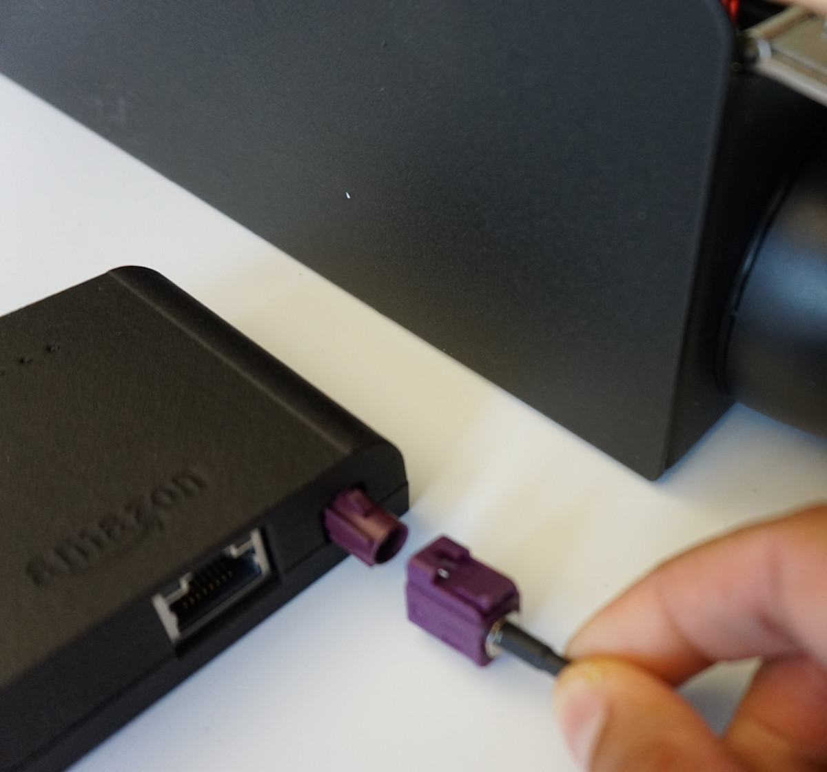
6. Attach the antenna connector to the device’s antenna port until it locks in place.
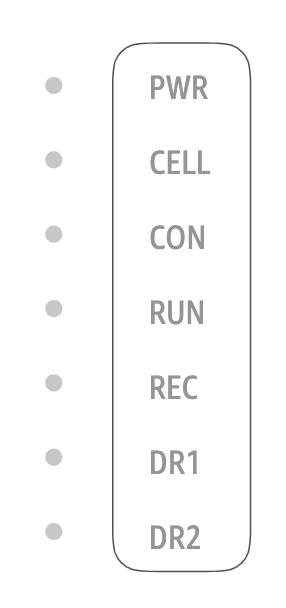
Step 4: LED and Connection terminal indicators
- PWR: Solid light indicates device is powered
- CELL:
- Flashingred light indicates no cellular coverage
- Flashingyellow light indicates low cellular coverage
- Solidgreen light indicates good cellular coverage
- Solidwhite light indicates the device is using Ethernet
- Flashingblue light indicates attempting to get cellular strength
- CON: Flashing light indicates device has Internet connectivity
- RUN: Flashing light indicates device is running as programmed
- REC: Solid light indicates device is in record mode and scanning for access credential (only occurs while provisioning a fob credential)
- DR1 and DR2: Solid light for 2 seconds indicates respective door is opening at that time.
Step 5: Device installation recommendations
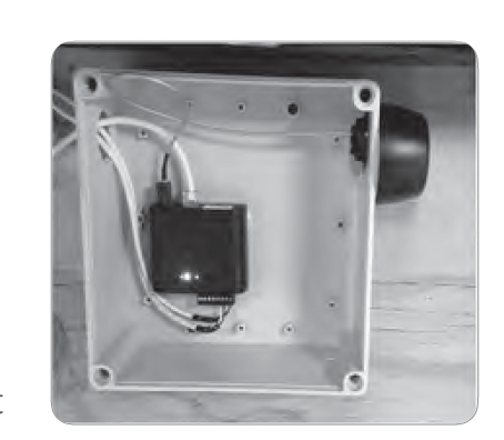
A. Device outside call box or existing junction box:
- Remove liner on 3M Stretch Release adhesive provided and place in two recesses provided on the back of device.
- Drill holes or remove knockouts from PVC junction box for wires and puck antenna mounting.
- Clean surface to which device will be installed with surface cleaning solvent like isopropyl alcohol or heptane.
- Mount puck antenna on the outside of PVC junction box following the steps in Section 3.
- Attach PVC junction box to wall with an appropriate fastener.
- Feed terminal block through hole in PVC Junction box and connect to Ring Access Controller Pro 2.
- Peel off liner on two 3M adhesive strips and mount Ring Access Controller Pro inside PVC junction box by pressing and holding for 30 seconds.
B. Device inside call Box:
- Clean installation surface with cleaning solvent.
- Peel off liner on two 3M adhesive strips.
- Alternatively, once all wires have been connected, place device in the call box so its position is secure without the requirement of fasteners to install device.
Ethernet cable (if applicable):
Once wires are connected to plug-in terminal, if Ethernet connector is available, insert the ethernet wire into connector array. Then connect the puck antenna to the antenna port as a back-up.
Power wire:
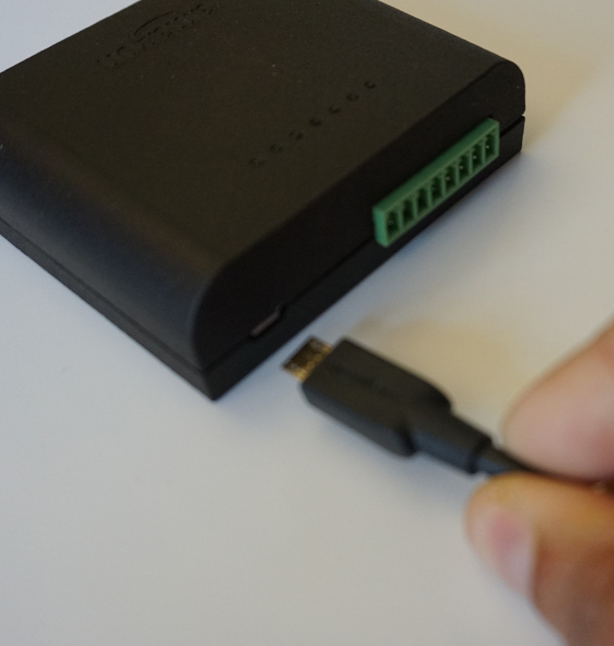
Device outside call box
Connect to power by inserting micro USB plug on the DC power supply brick and fold "Do Not Unplug" sticker on power cable 1-2'' from wall supply.
Device inside call box
Connect to power through 7 and 8 (see section 2) on the connector array. Positive and negative terminals are interchangeable (polarity agnostic). Place "Do Not Unplug" sticker on device without covering LED status lights or labels.